First determine whether the capacitor stays connected to a battery: fixed voltage and fixed charge give different predictions.
Geometry and dielectrics
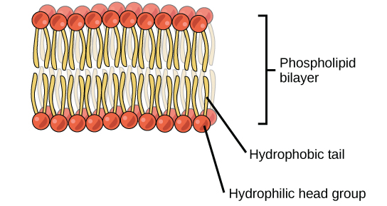
Capacitance C = Q/V measures charge stored per potential difference, in farads. For ideal parallel plates C = κε₀A/d, where A is plate area, d their separation, and κ the dielectric constant. Larger area or a dielectric increases capacitance; greater separation decreases it. Dielectricpolarization reduces the field for fixed free charge. With a battery attached, V stays fixed and Q changes; after disconnection, Q stays fixed and V changes. A cell membrane behaves approximately as a capacitor because conducting solutions are separated by an insulating lipid layer.
Stored energy is U = ½CV² = Q²/(2C) = ½QV. Parallel capacitors share voltage and their capacitances add. Series capacitors carry equal-magnitude charge in an initially uncharged ideal series network, and 1/Ceq = Σ1/C; the smaller capacitor has the larger voltage. A capacitor blocks steady direct current after charging in an ideal circuit. During charging through a resistor, the time constant is τ = RC; after one time constant the capacitor reaches about 63% of its final voltage.
Try before revealing the answer. A 2 µF capacitor is charged to 10 V and disconnected. A dielectric with κ = 4 fully fills the gap. Find final C, Q, V, and energy compared with the initial value.
Worked answer
C rises from 2 to 8 µF. Disconnection fixes Q = CV = 20 µC. Final V = Q/C = 2.5 V. Since U = Q²/(2C), energy falls to one quarter: from 100 µJ to 25 µJ. The energy change can appear as mechanical work during insertion.
19.5 Capacitors and Dielectrics — figures and tables
Figure 19.12 — 19.5 Capacitors and Dielectrics
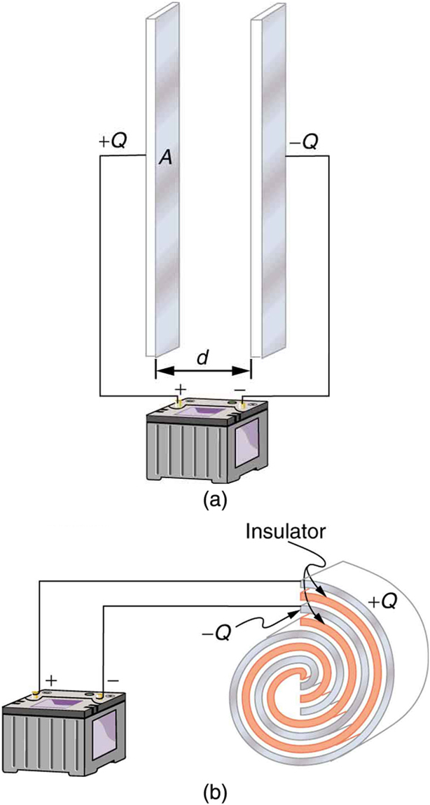
Figure 19.12 Both capacitors shown here were initially uncharged before being connected to a battery. They now have separated charges of + Q + Q and – Q – Q on their two halves. (a) A parallel plate capacitor. (b) A rolled capacitor with an insulating material between its two conducting sheets.
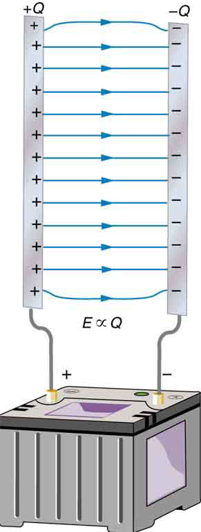
Figure 19.13 Electric field lines in this parallel plate capacitor, as always, start on positive charges and end on negative charges. Since the electric field strength is proportional to the density of field lines, it is also proportional to the amount of charge on the capacitor.
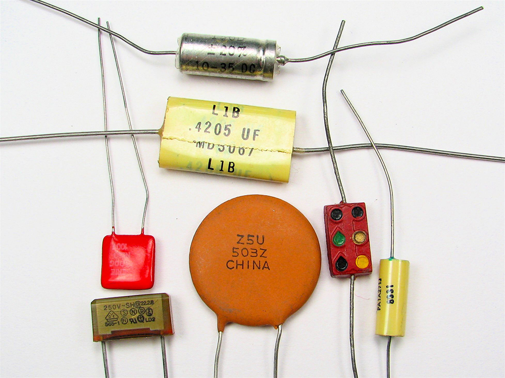
Figure 19.14 Some typical capacitors. Size and value of capacitance are not necessarily related. (credit: Windell Oskay)
Paul Peter Urone and Roger Hinrichs, College Physics 2E, OpenStax. (credit: Windell Oskay) · CC BY-NC-SA 4.0
· Original image ↗ · Access for free ↗Figure 19.15 — 19.5 Capacitors and Dielectrics
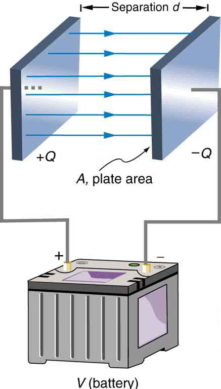
Figure 19.15 Parallel plate capacitor with plates separated by a distance d d . Each plate has an area A A .
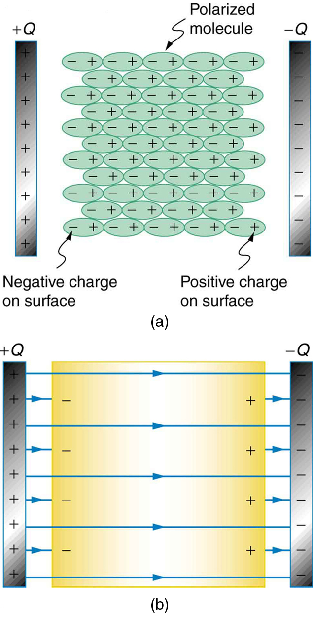
Figure 19.16 (a) The molecules in the insulating material between the plates of a capacitor are polarized by the charged plates. This produces a layer of opposite charge on the surface of the dielectric that attracts more charge onto the plate, increasing its capacitance. (b) The dielectric reduces the electric field strength inside the capacitor, resulting in a smaller voltage between the plates for the same charge. The capacitor stores the same charge for a smaller voltage, implying that it has a larger capacitance because of the dielectric.
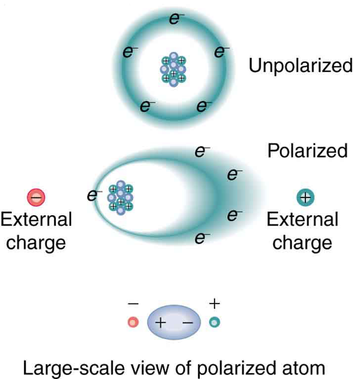
Figure 19.17 Artist’s conception of a polarized atom. The orbits of electrons around the nucleus are shifted slightly by the external charges (shown exaggerated). The resulting separation of charge within the atom means that it is polarized. Note that the unlike charge is now closer to the external charges, causing the polarization.
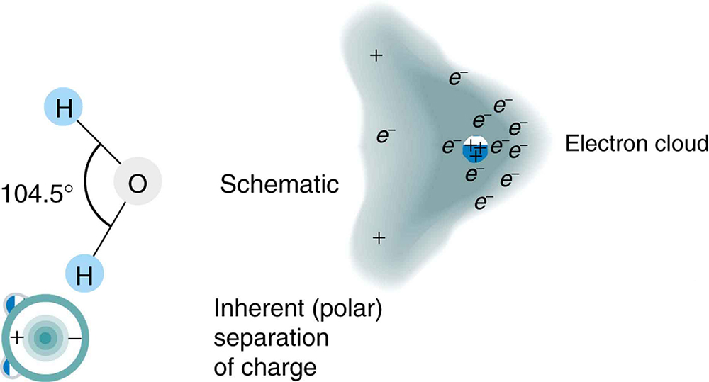
Figure 19.18 Artist’s conception of a water molecule. There is an inherent separation of charge, and so water is a polar molecule. Electrons in the molecule are attracted to the oxygen nucleus and leave an excess of positive charge near the two hydrogen nuclei. (Note that the schematic on the right is a rough illustration of the distribution of electrons in the water molecule. It does not show the actual numbers of protons and electrons involved in the structure.)
Table 19.1 Dielectric Constants and Dielectric Strengths for Various Materials at 20ºC. Paul Peter Urone and Roger Hinrichs, College Physics 2E, OpenStax.
19.6 Capacitors in Series and Parallel — figures and tables
Figure 19.19 — 19.6 Capacitors in Series and Parallel
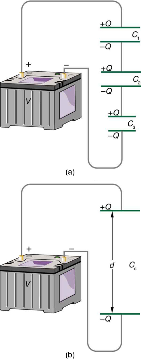
Figure 19.19 (a) Capacitors connected in series. The magnitude of the charge on each plate is Q Q . (b) An equivalent capacitor has a larger plate separation d d . Series connections produce a total capacitance that is less than that of any of the individual capacitors.
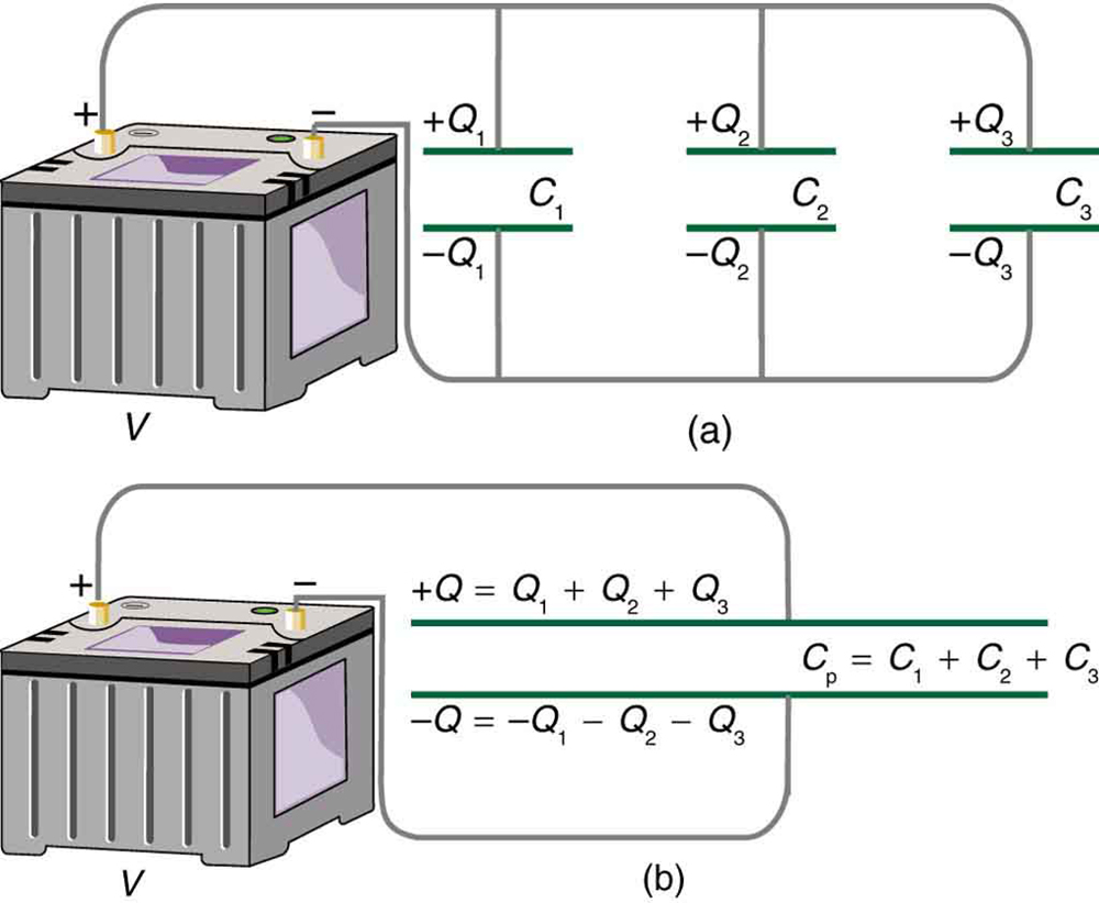
Figure 19.20 (a) Capacitors in parallel. Each is connected directly to the voltage source just as if it were all alone, and so the total capacitance in parallel is just the sum of the individual capacitances. (b) The equivalent capacitor has a larger plate area and can therefore hold more charge than the individual capacitors.
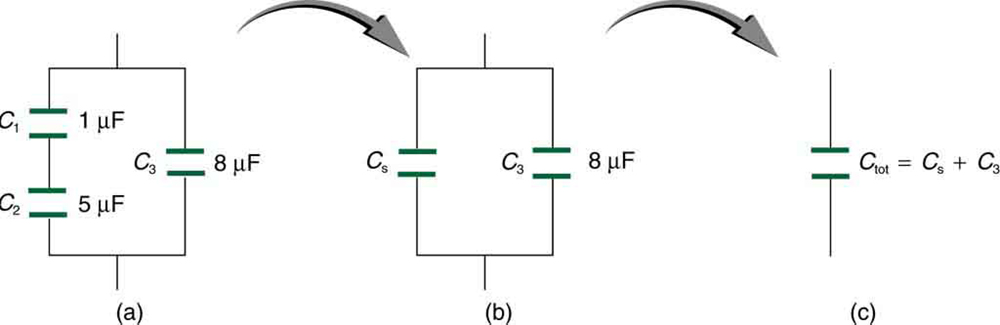
Figure 19.21 (a) This circuit contains both series and parallel connections of capacitors. See Example 19.10 for the calculation of the overall capacitance of the circuit. (b) C 1 C 1 and C 2 C 2 are in series; their equivalent capacitance C S C S is less than either of them. (c) Note that C S C S is in parallel with C 3 C 3 . The total capacitance is, thus, the sum of C S C S and C 3 C 3 .
19.7 Energy Stored in Capacitors — figures and tables
Figure 19.22 — 19.7 Energy Stored in Capacitors
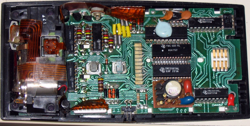
Figure 19.22 Energy stored in the large capacitor is used to preserve the memory of an electronic calculator when its batteries are charged. (credit: Kucharek, Wikimedia Commons)
Paul Peter Urone and Roger Hinrichs, College Physics 2E, OpenStax. (credit: Kucharek, Wikimedia Commons) · CC BY-NC-SA 4.0
· Original image ↗ · Access for free ↗Figure 19.23 — 19.7 Energy Stored in Capacitors
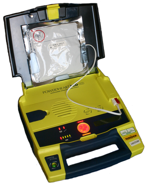
Figure 19.23 Automated external defibrillators are found in many public places. These portable units provide verbal instructions for use in the important first few minutes for a person suffering a cardiac attack. (credit: Owain Davies, Wikimedia Commons)
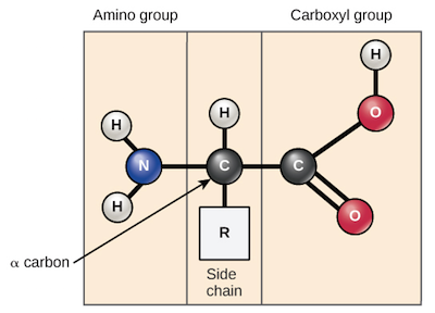
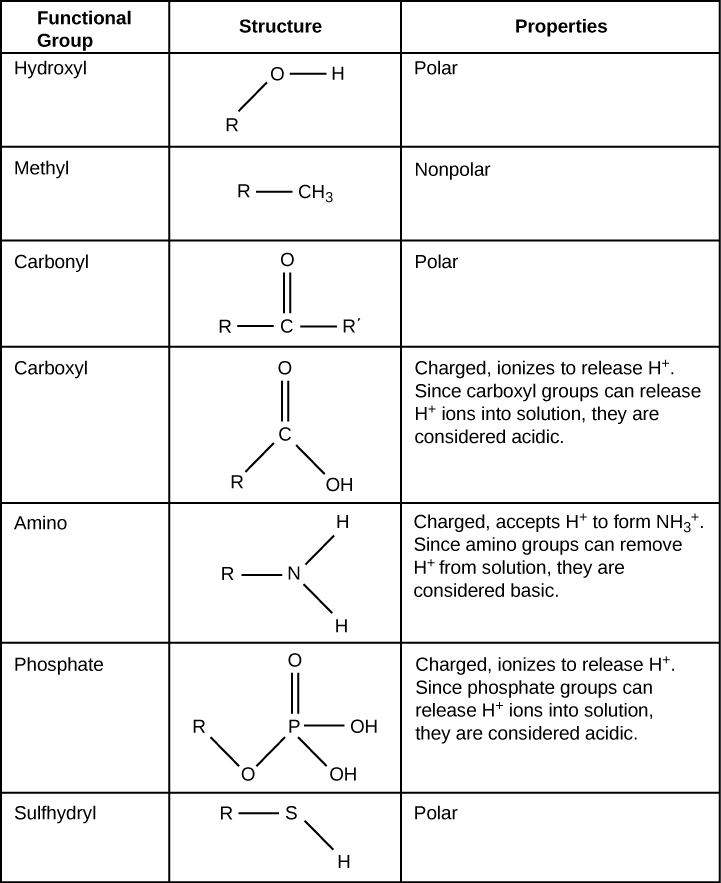
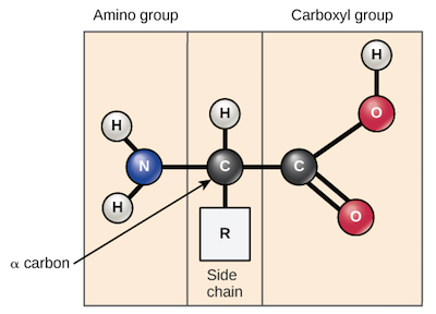
A nitrogen-containing functional group. A free amino acid’s amino group is typically protonated (NH₃⁺) near physiological pH; proline’s ring nitrogen is an exception to this formula.
Figure 19.12 Both capacitors shown here were initially uncharged before being connected to a battery. They now have separated charges of + Q + Q and – Q – Q on their two halves. (a) A parallel plate capacitor. (b) A rolled capacitor with an insulating material between its two conducting sheets.
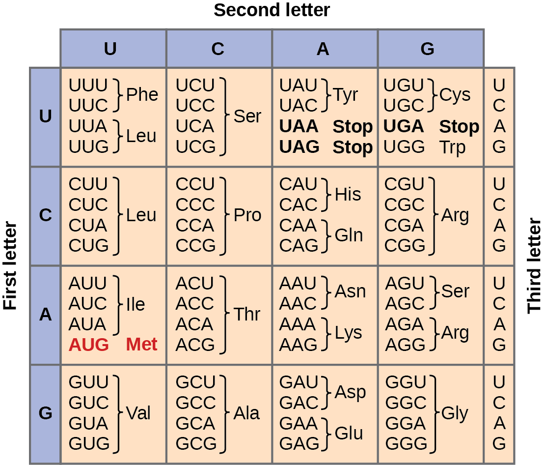
Figure 15.4 This figure shows the genetic code for translating each nucleotide triplet in mRNA into an amino acid or a termination signal in a protein. (credit: modification of work by NIH)
Figure 19.16 (a) The molecules in the insulating material between the plates of a capacitor are polarized by the charged plates. This produces a layer of opposite charge on the surface of the dielectric that attracts more charge onto the plate, increasing its capacitance. (b) The dielectric reduces the electric field strength inside the capacitor, resulting in a smaller voltage between the plates for the same charge. The capacitor stores the same charge for a smaller voltage, implying that it has a larger capacitance because of the dielectric.
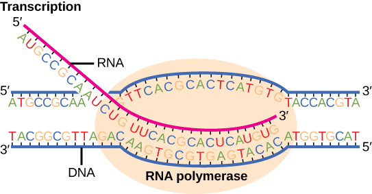
Figure 15.7 Messenger RNA is a copy of protein-coding information in the coding strand of DNA, with the substitution of U in the RNA for T in the coding sequence. However, new RNA nucleotides base pair with the nucleotides of the template strand. RNA is synthesized in its 5'-3' direction, using the enzyme RNA polymerase. As the template is read, the DNA unwinds ahead of the polymerase and then rewinds behind it.
An electrical property that can be positive or negative. Opposite charges attract and like charges repel; net charge is the sum of all charges on a particle.
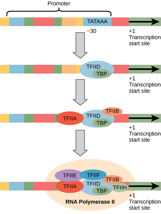
Figure 15.10 A generalized promoter of a gene transcribed by RNA polymerase II is shown. Transcription factors recognize the promoter. RNA polymerase II then binds and forms the transcription initiation complex.
The exponent needed to obtain a number from a chosen fixed number. For decimal logarithms, log₁₀(100) = 2 because 10² = 100; pH uses the negative decimal logarithm of hydrogen ion activity.
A thin boundary or sheet. Cell membranes are lipid bilayers containing proteins; blotting membranes are synthetic supports that hold proteins or nucleic acids for detection.
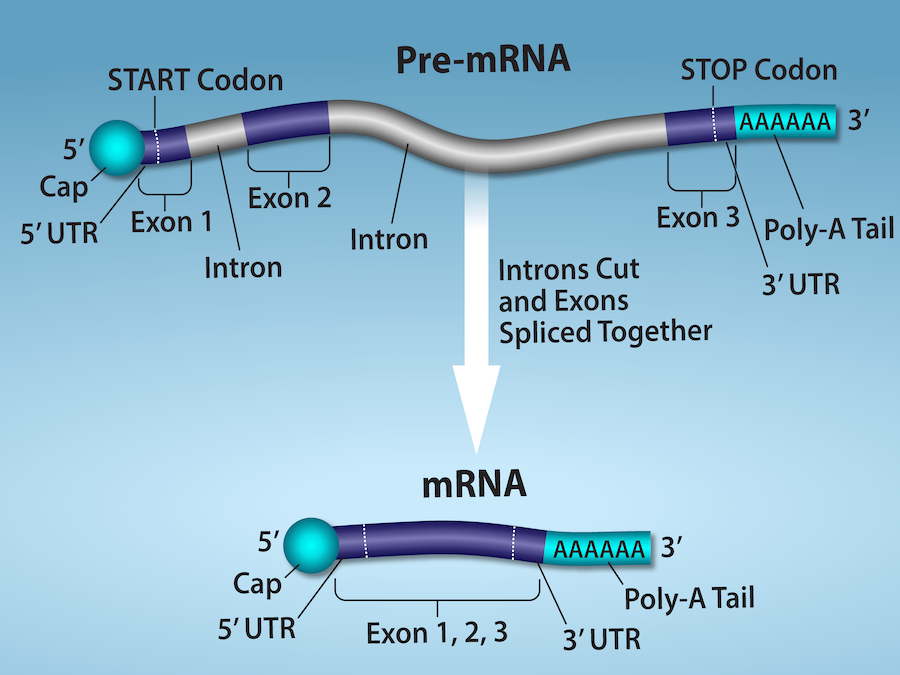
Figure 15.11 Eukaryotic pre-mRNA processing. In addition to 5’ Cap and 3’ Poly-A Tail addition, introns must be precisely removed and exons joined to generate a functional mRNA. Nucleotides upstream (towards the 5’cap) of the translation START codon are part of the 5’ untranslated region (5’ UTR). Nucleotides downstream (towards 3’end) of the STOP codon form the 3’ UTR. Both 5’ and 3’ UTRs are important for regulating translation initiation and mRNA stability. Credit: Rao, A., Ryan, K. Fletcher, S. and Tag, A. Department of Biology, Texas A&M University.
Rao, A., Ryan, K. Fletcher, S. and Tag, A. Department of Biology, Texas A&M University.; Mary Ann Clark, Matthew Douglas, and Jung Choi, Biology 2e, OpenStax. · CC BY-NC-SA 4.0
· Original image ↗ · Access for free ↗
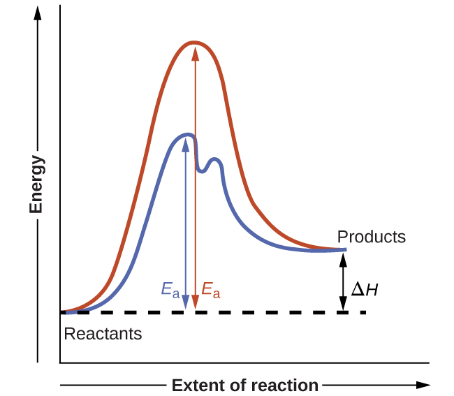
Figure 12.19 Reaction diagrams for an endothermic process in the absence (red curve) and presence (blue curve) of a catalyst. The catalyzed pathway involves a two-step mechanism (note the presence of two transition states) and an intermediate species (represented by the valley between the two transitions states).
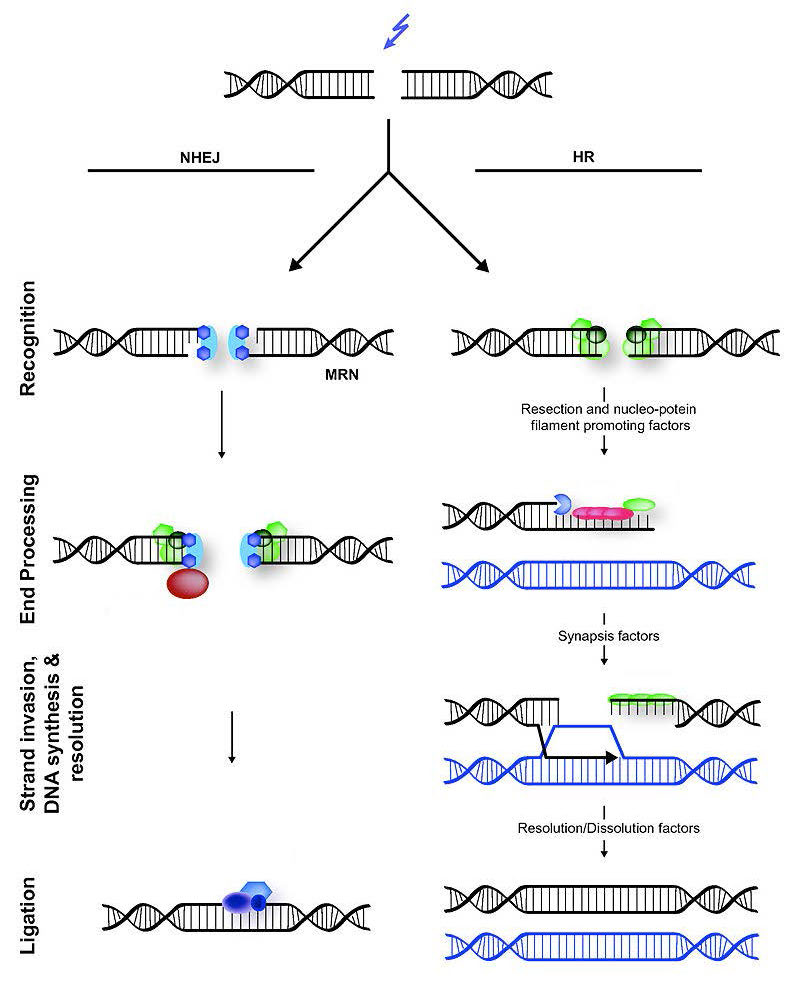
Figure 7.45 - Non-homologous end joining (left) versus homologous recombination (right) - Wikipedia
Wikipedia, as credited by Kevin Ahern, Indira Rajagopal, and Taralyn Tan, Biochemistry Free For All, Oregon State University, via Biology LibreTexts. · Source attribution
· Original image ↗ · Access for free ↗
The amount of a substance that can dissolve in a solvent under specified conditions. Soluble means able to dissolve; insoluble means only very slightly soluble in that solvent.
Figure 15.7 Messenger RNA is a copy of protein-coding information in the coding strand of DNA, with the substitution of U in the RNA for T in the coding sequence. However, new RNA nucleotides base pair with the nucleotides of the template strand. RNA is synthesized in its 5'-3' direction, using the enzyme RNA polymerase. As the template is read, the DNA unwinds ahead of the polymerase and then rewinds behind it.
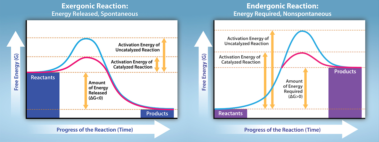
A fleeting, high-energy arrangement at a reaction barrier. It is an energy maximum along the reaction path, rather than a stable reaction intermediate.
Figure 12.19 Reaction diagrams for an endothermic process in the absence (red curve) and presence (blue curve) of a catalyst. The catalyzed pathway involves a two-step mechanism (note the presence of two transition states) and an intermediate species (represented by the valley between the two transitions states).
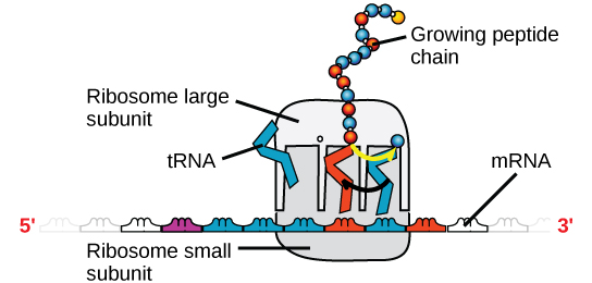
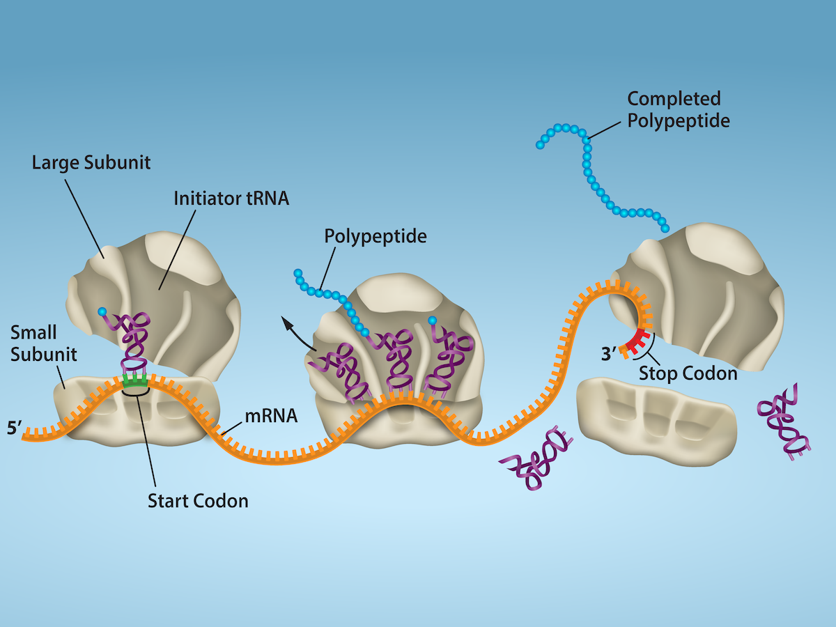
Figure 15.18 Translation begins when an initiator tRNA anticodon recognizes a start codon on mRNA bound to a small ribosomal subunit. The large ribosomal subunit joins the small subunit, and a second tRNA is recruited. As the mRNA moves relative to the ribosome, successive tRNAs move through the ribosome and the polypeptide chain is formed. Entry of a release factor into the A site terminates translation and the components dissociate.
No matching terms. Try a different name or abbreviation.
19.5 Capacitors and Dielectrics
OpenStax · 19.5 Capacitors and Dielectrics ↗ Instructional page including learning objectives, examples, figures, source tables and questions. Site navigation and embedded media players are omitted; source media links remain available.
A capacitor is a device used to store electric charge. Capacitors have applications ranging from filtering static out of radio reception to energy storage in heart defibrillators. Typically, commercial capacitors have two conducting parts close to one another, but not touching, such as those in Figure 19.12. (Most of the time an insulator is used between the two plates to provide separation—see the discussion on dielectrics below.) When battery terminals are connected to an initially uncharged capacitor, equal amounts of positive and negative charge, and , are separated into its two plates. The capacitor remains neutral overall, but we refer to it as storing a charge in this circumstance.
Figure 19.12 Both capacitors shown here were initially uncharged before being connected to a battery. They now have separated charges of + Q + Q and – Q – Q on their two halves. (a) A parallel plate capacitor. (b) A rolled capacitor with an insulating material between its two conducting sheets.
The amount of charge a capacitor can store depends on two major factors—the voltage applied and the capacitor’s physical characteristics, such as its size.
The amount of charge a capacitor can store depends on two major factors—the voltage applied and the capacitor’s physical characteristics, such as its size.
A system composed of two identical, parallel conducting plates separated by a distance, as in Figure 19.13, is called a parallel plate capacitor. It is easy to see the relationship between the voltage and the stored charge for a parallel plate capacitor, as shown in Figure 19.13. Each electric field line starts on an individual positive charge and ends on a negative one, so that there will be more field lines if there is more charge. (Drawing a single field line per charge is a convenience, only. We can draw many field lines for each charge, but the total number is proportional to the number of charges.) The electric field strength is, thus, directly proportional to .
Figure 19.13 — 19.5 Capacitors and Dielectrics
Figure 19.13 Electric field lines in this parallel plate capacitor, as always, start on positive charges and end on negative charges. Since the electric field strength is proportional to the density of field lines, it is also proportional to the amount of charge on the capacitor.
This is true in general: The greater the voltage applied to any capacitor, the greater the charge stored in it.
Different capacitors will store different amounts of charge for the same applied voltage, depending on their physical characteristics. We define their capacitance to be such that the charge stored in a capacitor is proportional to . The charge stored in a capacitor is given by
19.48
This equation expresses the two major factors affecting the amount of charge stored. Those factors are the physical characteristics of the capacitor, , and the voltage, . Rearranging the equation, we see that capacitance is the amount of charge stored per volt, or
The unit of capacitance is the farad (F), named for Michael Faraday (1791–1867), an English scientist who contributed to the fields of electromagnetism and electrochemistry. Since capacitance is charge per unit voltage, we see that a farad is a coulomb per volt, or
19.51
A 1-farad capacitor would be able to store 1 coulomb (a very large amount of charge) with the application of only 1 volt. One farad is, thus, a very large capacitance. Typical capacitors range from fractions of a picofarad to millifarads .
Figure 19.14 shows some common capacitors. Capacitors are primarily made of ceramic, glass, or plastic, depending upon purpose and size. Insulating materials, called dielectrics, are commonly used in their construction, as discussed below.
Figure 19.14 — 19.5 Capacitors and Dielectrics
Figure 19.14 Some typical capacitors. Size and value of capacitance are not necessarily related. (credit: Windell Oskay)
The parallel plate capacitor shown in Figure 19.15 has two identical conducting plates, each having a surface area , separated by a distance (with no material between the plates). When a voltage is applied to the capacitor, it stores a charge, as shown. We can see how its capacitance depends on and by considering the characteristics of the Coulomb force. We know that like charges repel, unlike charges attract, and the force between charges decreases with distance. So it seems quite reasonable that the bigger the plates are, the more charge they can store—because the charges can spread out more. Thus should be greater for larger . Similarly, the closer the plates are together, the greater the attraction of the opposite charges on them. So should be greater for smaller .
Figure 19.15 — 19.5 Capacitors and Dielectrics
Figure 19.15 Parallel plate capacitor with plates separated by a distance d d . Each plate has an area A A .
It can be shown that for a parallel plate capacitor there are only two factors ( and ) that affect its capacitance . The capacitance of a parallel plate capacitor in equation form is given by
is the area of one plate in square meters, and
is the distance between the plates in meters. The constant
is the permittivity of free space; its numerical value in SI units is
.
The units of F/m are equivalent to . The small numerical value of is related to the large size of the farad. A parallel plate capacitor must have a large area to have a capacitance approaching a farad. (Note that the above equation is valid when the parallel plates are separated by air or free space. When another material is placed between the plates, the equation is modified, as discussed below.)
(a) What is the capacitance of a parallel plate capacitor with metal plates, each of area , separated by 1.00 mm? (b) What charge is stored in this capacitor if a voltage of is applied to it?
Strategy
Finding the capacitance is a straightforward application of the equation . Once is found, the charge stored can be found using the equation .
Entering the given values into the equation for the capacitance of a parallel plate capacitor yields
19.54
Discussion for (a)
This small value for the capacitance indicates how difficult it is to make a device with a large capacitance. Special techniques help, such as using very large area thin foils placed close together.
The charge stored in any capacitor is given by the equation . Entering the known values into this equation gives
19.55
Discussion for (b)
This charge is only slightly greater than those found in typical static electricity. Since air breaks down at about , more charge cannot be stored on this capacitor by increasing the voltage.
Another interesting biological example dealing with electric potential is found in the cell’s plasma membrane. The membrane sets a cell off from its surroundings and also allows ions to selectively pass in and out of the cell. There is a potential difference across the membrane of about . This is due to the mainly negatively chargedions in the cell and the predominance of positively charged sodium () ions outside. Things change when a nerve cell is stimulated. ions are allowed to pass through the membrane into the cell, producing a positive membrane potential—the nerve signal. The cell membrane is about 7 to 10 nm thick. An approximate value of the electric field across it is given by
19.56
This electric field is enough to cause a breakdown in air.
The previous example highlights the difficulty of storing a large amount of charge in capacitors. If is made smaller to produce a larger capacitance, then the maximum voltage must be reduced proportionally to avoid breakdown (since ). An important solution to this difficulty is to put an insulating material, called a dielectric, between the plates of a capacitor and allow
to be as small as possible. Not only does the smaller make the capacitance greater, but many insulators can withstand greater electric fields than air before breaking down.
Values of the dielectric constant for various materials are given in Table 19.1. Note that for vacuum is exactly 1, and so the above equation is valid in that case, too. If a dielectric is used, perhaps by placing Teflon between the plates of the capacitor in Example 19.8, then the capacitance is greater by the factor , which for Teflon is 2.1.
How large a capacitor can you make using a chewing gum wrapper? The plates will be the aluminum foil, and the separation (dielectric) in between will be the paper.
Table
19.1
Dielectric Constants and Dielectric Strengths for Various Materials at 20ºC
Note also that the dielectric constant for air is very close to 1, so that air-filled capacitors act much like those with vacuum between their plates except that the air can become conductive if the electric field strength becomes too great. (Recall that for a parallel plate capacitor.) Also shown in Table 19.1 are maximum electric field strengths in V/m, called dielectric strengths, for several materials. These are the fields above which the material begins to break down and conduct. The dielectric strength imposes a limit on the voltage that can be applied for a given plate separation. For instance, in Example 19.8, the separation is 1.00 mm, and so the voltage limit for air is
19.58
However, the limit for a 1.00 mm separation filled with Teflon is 60,000 V, since the dielectric strength of Teflon is V/m. So the same capacitor filled with Teflon has a greater capacitance and can be subjected to a much greater voltage. Using the capacitance we calculated in the above example for the air-filled parallel plate capacitor, we find that the Teflon-filled capacitor can store a maximum charge of
19.59
This is 42 times the charge of the same air-filled capacitor.
The maximum electric field strength above which an insulating material begins to break down and conduct is called its dielectric strength.
Microscopically, how does a dielectric increase capacitance? Polarization of the insulator is responsible. The more easily it is polarized, the greater its dielectric constant . Water, for example, is a polarmolecule because one end of the molecule has a slight positive charge and the other end has a slight negative charge. The polarity of water causes it to have a relatively large dielectric constant of 80. The effect of polarization can be best explained in terms of the characteristics of the Coulomb force. Figure 19.16 shows the separation of charge schematically in the molecules of a dielectric material placed between the charged plates of a capacitor. The Coulomb force between the closest ends of the molecules and the charge on the plates is attractive and very strong, since they are very close together. This attracts more charge onto the plates than if the space were empty and the opposite charges were a distance away.
Figure 19.16 — 19.5 Capacitors and Dielectrics
Figure 19.16 (a) The molecules in the insulating material between the plates of a capacitor are polarized by the charged plates. This produces a layer of opposite charge on the surface of the dielectric that attracts more charge onto the plate, increasing its capacitance. (b) The dielectric reduces the electric field strength inside the capacitor, resulting in a smaller voltage between the plates for the same charge. The capacitor stores the same charge for a smaller voltage, implying that it has a larger capacitance because of the dielectric.
Another way to understand how a dielectric increases capacitance is to consider its effect on the electric field inside the capacitor. Figure 19.16(b) shows the electric field lines with a dielectric in place. Since the field lines end on charges in the dielectric, there are fewer of them going from one side of the capacitor to the other. So the electric field strength is less than if there were a vacuum between the plates, even though the same charge is on the plates. The voltage between the plates is , so it too is reduced by the dielectric. Thus there is a smaller voltage for the same charge; since , the capacitance is greater.
Polarization is a separation of charge within an atom or molecule. As has been noted, the planetary model of the atom pictures it as having a positive nucleus orbited by negative electrons, analogous to the planets orbiting the Sun. Although this model is not completely accurate, it is very helpful in explaining a vast range of phenomena and will be refined elsewhere, such as in Atomic Physics. The submicroscopic origin of polarization can be modeled as shown in Figure 19.17.
Figure 19.17 — 19.5 Capacitors and Dielectrics
Figure 19.17 Artist’s conception of a polarized atom. The orbits of electrons around the nucleus are shifted slightly by the external charges (shown exaggerated). The resulting separation of charge within the atom means that it is polarized. Note that the unlike charge is now closer to the external charges, causing the polarization.
We will find in Atomic Physics that the orbits of electrons are more properly viewed as electron clouds with the density of the cloud related to the probability of finding an electron in that location (as opposed to the definite locations and paths of planets in their orbits around the Sun). This cloud is shifted by the Coulomb force so that the atom on average has a separation of charge. Although the atom remains neutral, it can now be the source of a Coulomb force, since a charge brought near the atom will be closer to one type of charge than the other.
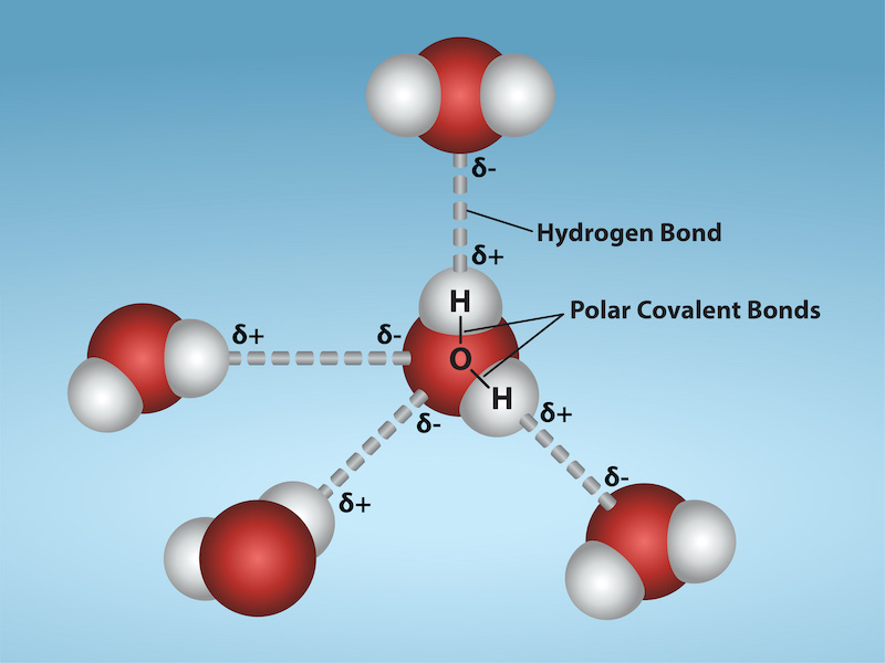
Some molecules, such as those of water, have an inherent separation of charge and are thus called polarmolecules. Figure 19.18 illustrates the separation of charge in a water molecule, which has two hydrogen atoms and one oxygen atom . The water molecule is not symmetric—the hydrogen atoms are repelled to one side, giving the molecule a boomerang shape. The electrons in a water molecule are more concentrated around the more highly charged oxygen nucleus than around the hydrogen nuclei. This makes the oxygen end of the molecule slightly negative and leaves the hydrogen ends slightly positive. The inherent separation of charge in polarmolecules makes it easier to align them with external fields and charges. Polarmolecules therefore exhibit greater polarization effects and have greater dielectric constants. Those who study chemistry will find that the polar nature of water has many effects. For example, water molecules gather ions much more effectively because they have an electric field and a separation of charge to attract charges of both signs. Also, as brought out in the previous chapter, polar water provides a shield or screening of the electric fields in the highly chargedmolecules of interest in biological systems.
Figure 19.18 — 19.5 Capacitors and Dielectrics
Figure 19.18 Artist’s conception of a water molecule. There is an inherent separation of charge, and so water is a polar molecule. Electrons in the molecule are attracted to the oxygen nucleus and leave an excess of positive charge near the two hydrogen nuclei. (Note that the schematic on the right is a rough illustration of the distribution of electrons in the water molecule. It does not show the actual numbers of protons and electrons involved in the structure.)
OpenStax · 19.6 Capacitors in Series and Parallel ↗ Instructional page including learning objectives, examples, figures, source tables and questions. Site navigation and embedded media players are omitted; source media links remain available.
Learning Objectives
By the end of this section, you will be able to:
Derive expressions for total capacitance in series and in parallel.
Identify series and parallel parts in the combination of connection of capacitors.
Calculate the effective capacitance in series and parallel given individual capacitances.
Several capacitors may be connected together in a variety of applications. Multiple connections of capacitors act like a single equivalent capacitor. The total capacitance of this equivalent single capacitor depends both on the individual capacitors and how they are connected. There are two simple and common types of connections, called series and parallel, for which we can easily calculate the total capacitance. Certain more complicated connections can also be related to combinations of series and parallel.
Figure 19.19(a) shows a series connection of three capacitors with a voltage applied. As for any capacitor, the capacitance of the combination is related to charge and voltage by .
Note in Figure 19.19 that opposite charges of magnitude flow to either side of the originally uncharged combination of capacitors when the voltage is applied. Conservation of charge requires that equal-magnitude charges be created on the plates of the individual capacitors, since charge is only being separated in these originally neutral devices. The end result is that the combination resembles a single capacitor with an effective plate separation greater than that of the individual capacitors alone. (See Figure 19.19(b).) Larger plate separation means smaller capacitance. It is a general feature of series connections of capacitors that the total capacitance is less than any of the individual capacitances.
Figure 19.19 — 19.6 Capacitors in Series and Parallel
Figure 19.19 (a) Capacitors connected in series. The magnitude of the charge on each plate is Q Q . (b) An equivalent capacitor has a larger plate separation d d . Series connections produce a total capacitance that is less than that of any of the individual capacitors.
We can find an expression for the total capacitance by considering the voltage across the individual capacitors shown in Figure 19.19. Solving for gives . The voltages across the individual capacitors are thus , , and . The total voltage is the sum of the individual voltages:
Canceling the s, we obtain the equation for the total capacitance in series to be
19.63
where “...” indicates that the expression is valid for any number of capacitors connected in series. An expression of this form always results in a total capacitance that is less than any of the individual capacitances , , ..., as the next example illustrates.
Entering the given capacitances into the expression for gives .
19.64
Inverting to find yields .
Discussion
The total series capacitance is less than the smallest individual capacitance, as promised. In series connections of capacitors, the sum is less than the parts. In fact, it is less than any individual. Note that it is sometimes possible, and more convenient, to solve an equation like the above by finding the least common denominator, which in this case (showing only whole-number calculations) is 40. Thus,
19.65
so that
19.66
Capacitors in Parallel
Figure 19.20(a) shows a parallel connection of three capacitors with a voltage applied. Here the total capacitance is easier to find than in the series case. To find the equivalent total capacitance , we first note that the voltage across each capacitor is , the same as that of the source, since they are connected directly to it through a conductor. (Conductors are equipotentials, and so the voltage across the capacitors is the same as that across the voltage source.) Thus the capacitors have the same charges on them as they would have if connected individually to the voltage source. The total charge is the sum of the individual charges:
19.67
Figure 19.20 — 19.6 Capacitors in Series and Parallel
Figure 19.20 (a) Capacitors in parallel. Each is connected directly to the voltage source just as if it were all alone, and so the total capacitance in parallel is just the sum of the individual capacitances. (b) The equivalent capacitor has a larger plate area and can therefore hold more charge than the individual capacitors.
Using the relationship , we see that the total charge is , and the individual charges are , , and . Entering these into the previous equation gives
19.68
Canceling from the equation, we obtain the equation for the total capacitance in parallel
:
19.69
Total capacitance in parallel is simply the sum of the individual capacitances. (Again the “...” indicates the expression is valid for any number of capacitors connected in parallel.) So, for example, if the capacitors in the example above were connected in parallel, their capacitance would be
19.70
The equivalent capacitor for a parallel connection has an effectively larger plate area and, thus, a larger capacitance, as illustrated in Figure 19.20(b).
More complicated connections of capacitors can sometimes be combinations of series and parallel. (See Figure 19.21.) To find the total capacitance of such combinations, we identify series and parallel parts, compute their capacitances, and then find the total.
Figure 19.21 — 19.6 Capacitors in Series and Parallel
Figure 19.21 (a) This circuit contains both series and parallel connections of capacitors. See Example 19.10 for the calculation of the overall capacitance of the circuit. (b) C 1 C 1 and C 2 C 2 are in series; their equivalent capacitance C S C S is less than either of them. (c) Note that C S C S is in parallel with C 3 C 3 . The total capacitance is, thus, the sum of C S C S and C 3 C 3 .
Find the total capacitance of the combination of capacitors shown in Figure 19.21. Assume the capacitances in Figure 19.21 are known to three decimal places (
, , and ), and round your answer to three decimal places.
Strategy
To find the total capacitance, we first identify which capacitors are in series and which are in parallel. Capacitors and are in series. Their combination, labeled in the figure, is in parallel with .
Since and are in series, their total capacitance is given by . Entering their values into the equation gives
19.71
Inverting gives
19.72
This equivalent series capacitance is in parallel with the third capacitor; thus, the total is the sum
19.73
Discussion
This technique of analyzing the combinations of capacitors piece by piece until a total is obtained can be applied to larger combinations of capacitors.
19.7 Energy Stored in Capacitors
OpenStax · 19.7 Energy Stored in Capacitors ↗ Instructional page including learning objectives, examples, figures, source tables and questions. Site navigation and embedded media players are omitted; source media links remain available.
Learning Objectives
By the end of this section, you will be able to:
List some uses of capacitors.
Express in equation form the energy stored in a capacitor.
Explain the function of a defibrillator.
Most of us have seen dramatizations in which medical personnel use a defibrillator to pass an electric current through a patient’s heart to get it to beat normally. (Review Figure 19.22.) Often realistic in detail, the person applying the shock directs another person to “make it 400 joules this time.” The energy delivered by the defibrillator is stored in a capacitor and can be adjusted to fit the situation. SI units of joules are often employed. Less dramatic is the use of capacitors in microelectronics, such as certain handheld calculators, to supply energy when batteries are charged. (See Figure 19.22.) Capacitors are also used to supply energy for flash lamps on cameras.
Figure 19.22 — 19.7 Energy Stored in Capacitors
Figure 19.22 Energy stored in the large capacitor is used to preserve the memory of an electronic calculator when its batteries are charged. (credit: Kucharek, Wikimedia Commons)
Energy stored in a capacitor is electrical potential energy, and it is thus related to the charge and voltage on the capacitor. We must be careful when applying the equation for electrical potential energy to a capacitor. Remember that is the potential energy of a charge going through a voltage . But the capacitor starts with zero voltage and gradually comes up to its full voltage as it is charged. The first charge placed on a capacitor experiences a change in voltage , since the capacitor has zero voltage when uncharged. The final charge placed on a capacitor experiences , since the capacitor now has its full voltage on it. The average voltage on the capacitor during the charging process is , and so the average voltage experienced by the full charge is . Thus the energy stored in a capacitor, , is
19.74
where is the charge on a capacitor with a voltage applied. (Note that the energy is not , but .) Charge and voltage are related to the capacitance of a capacitor by , and so the expression for can be algebraically manipulated into three equivalent expressions:
19.75
where is the charge and the voltage on a capacitor . The energy is in joules for a charge in coulombs, voltage in volts, and capacitance in farads.
Energy Stored in Capacitors
The energy stored in a capacitor can be expressed in three ways:
19.76
where is the charge, is the voltage, and is the capacitance of the capacitor. The energy is in joules for a charge in coulombs, voltage in volts, and capacitance in farads.
In a defibrillator, the delivery of a large charge in a short burst to a set of paddles across a person’s chest can be a lifesaver. The person’s heart attack might have arisen from the onset of fast, irregular beating of the heart—cardiac or ventricular fibrillation. The application of a large shock of electrical energy can terminate the arrhythmia and allow the body’s pacemaker to resume normal patterns. Today it is common for ambulances to carry a defibrillator, which also uses an electrocardiogram to analyze the patient’s heartbeat pattern. Automated external defibrillators (AED) are found in many public places (Figure 19.23). These are designed to be used by lay persons. The device automatically diagnoses the patient’s heart condition and then applies the shock with appropriate energy and waveform. CPR is recommended in many cases before use of an AED.
Figure 19.23 — 19.7 Energy Stored in Capacitors
Figure 19.23 Automated external defibrillators are found in many public places. These portable units provide verbal instructions for use in the important first few minutes for a person suffering a cardiac attack. (credit: Owain Davies, Wikimedia Commons)