Foundation 4 · 4C · Electricity, magnetism, and electrochemistry

Current, , and measurements

Sources ↗

Current is conserved at junctions; voltage changes sum to zero around a closed loop.

Current and circuit bookkeeping

Current I = ΔQ/Δt is measured in amperes, or coulombs per second. Conventional current follows positive- motion; in a metal drift oppositely. is energy supplied per by a source, measured in volts despite its name. A real source with internal r has terminal voltage V = ε − while delivering current. Kirchhoff’s junction rule conserves ; the loop rule conserves energy. Electrical is P = IV and, for an ohmic resistor, also I²R or V²/R.

Source: College Physics 2E 20 — Section Summary · 21.4 DC Voltmeters and Ammeters

from material and geometry

An ohmic element satisfies V = at constant physical conditions. R = ρL/A depends on material , length, and cross-sectional area; has units Ω·m. Series resistors carry the same current and have Req = ΣR. Parallel resistors have the same voltage and satisfy 1/Req = Σ1/R. A parallel combination is less resistive than its smallest branch resistor. Metal usually increases with temperature; nonlinear and changing temperatures can invalidate a fixed- approximation.

Source: College Physics 2E 20 — Section Summary · 21.4 DC Voltmeters and Ammeters

Measure current and voltage correctly

An belongs in series and ideally has zero , so the current changes negligibly. A belongs in parallel and ideally has infinite , so it draws negligible current. Connecting an directly across a source creates a low- path. Metals conduct primarily by ; electrolyte conduct by both and , which move in opposite directions but contribute to conventional current in the same direction. Ionic , , and mobility affect conductivity; conductivity alone does not identify a specific .

Source: College Physics 2E 20 — Section Summary · 21.4 DC Voltmeters and Ammeters

Apply it

Try before revealing the answer. A 6 Ω and a 3 Ω resistor are connected in parallel across an ideal 12 V battery. Find equivalent , branch currents, and total .

Worked answer

1/Req = 1/6 + 1/3 = 1/2, so Req = 2 Ω. Currents are 12/6 = 2 A and 12/3 = 4 A; total current is 6 A. Total is 12 × 6 = 72 W, also 24 W + 48 W across the branches.

Source: College Physics 2E 20 — Section Summary · 21.4 DC Voltmeters and Ammeters

21.4 DC Voltmeters and Ammeters — figures and tables
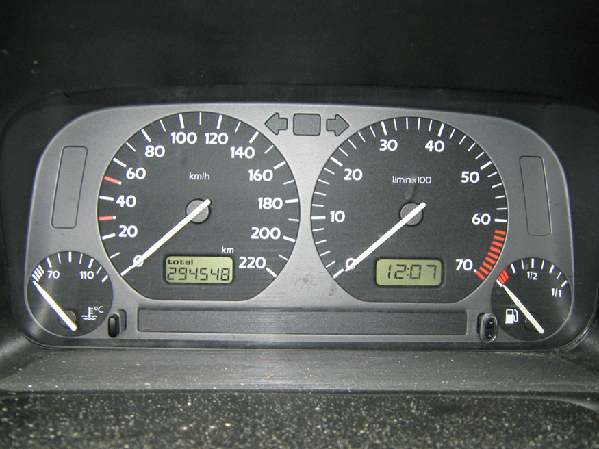
This photograph shows the instruments on a gray Volkswagen Vento dashboard, including the speedometer, odometer, and fuel and temperature gauges, showing some readings.
Figure 21.26 — 21.4 DC Voltmeters and Ammeters

Figure 21.26 The fuel and temperature gauges (far right and far left, respectively) in this 1996 Volkswagen are voltmeters that register the voltage output of “sender” units, which are hopefully proportional to the amount of gasoline in the tank and the engine temperature. (credit: Christian Giersing)

Paul Peter Urone and Roger Hinrichs, College Physics 2E, OpenStax. (credit: Christian Giersing) · CC BY-NC-SA 4.0 · Original image ↗ · Access for free ↗
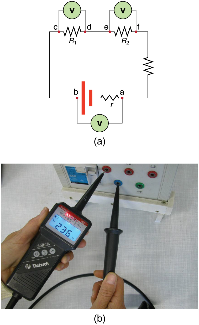
Part a shows a schematic drawing of a circuit with a voltage source and its internal resistance, in series with two load resistors R sub one and R sub two having two probes of a voltmeter connected in parallel with each component. There is another resistor in series to close the circuit. Part b shows a photograph of a black voltmeter connected to two inputs on an electrical device, with a digital readout of the voltage across the source as an L E D display.
Figure 21.27 — 21.4 DC Voltmeters and Ammeters

Figure 21.27 (a) To measure potential differences in this series circuit, the voltmeter (V) is placed in parallel with the voltage source or either of the resistors. Note that terminal voltage is measured between points a and b. It is not possible to connect the voltmeter directly across the emf without including its internal resistance, r r . (b) A digital voltmeter in use. (credit: Messtechniker, Wikimedia Commons)

Paul Peter Urone and Roger Hinrichs, College Physics 2E, OpenStax. (credit: Messtechniker, Wikimedia Commons) · CC BY-NC-SA 4.0 · Original image ↗ · Access for free ↗
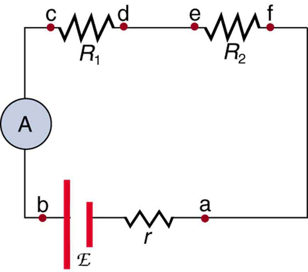
The diagram of an electric circuit shows a voltage source of e m f script E and internal resistance r and two resistive loads R sub one and R sub two. All are connected in series with an ammeter A.
Figure 21.28 — 21.4 DC Voltmeters and Ammeters

Figure 21.28 An ammeter (A) is placed in series to measure current. All of the current in this circuit flows through the meter. The ammeter would have the same reading if located between points d and e or between points f and a as it does in the position shown. (Note that the script capital E stands for emf, and r r stands for the internal resistance of the source of potential difference.)

Paul Peter Urone and Roger Hinrichs, College Physics 2E, OpenStax. · CC BY-NC-SA 4.0 · Original image ↗ · Access for free ↗

The drawing shows a voltmeter, which is a circuit with a large resistance in series with a galvanometer, along with its internal resistance.
Figure 21.29 — 21.4 DC Voltmeters and Ammeters

Figure 21.29 A large resistance R R placed in series with a galvanometer G produces a voltmeter, the full-scale deflection of which depends on the choice of R R . The larger the voltage to be measured, the larger R R must be. (Note that r r represents the internal resistance of the galvanometer.)

Paul Peter Urone and Roger Hinrichs, College Physics 2E, OpenStax. · CC BY-NC-SA 4.0 · Original image ↗ · Access for free ↗
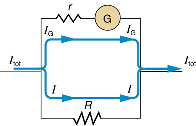
A resistance R is placed in parallel with a galvanometer G having an internal resistance r to produce an ammeter.
Figure 21.30 — 21.4 DC Voltmeters and Ammeters

Figure 21.30 A small shunt resistance R R placed in parallel with a galvanometer G produces an ammeter, the full-scale deflection of which depends on the choice of R R . The larger the current to be measured, the smaller R R must be. Most of the current ( I I ) flowing through the meter is shunted through R R to protect the galvanometer. (Note that r r represents the internal resistance of the galvanometer.) Ammeters may also have multiple scales for greater flexibility in application. The various scales are achieved by switching various shunt resistances in parallel with the galvanometer—the greater the maximum current to be measured, the smaller the shunt resistance must be.

Paul Peter Urone and Roger Hinrichs, College Physics 2E, OpenStax. · CC BY-NC-SA 4.0 · Original image ↗ · Access for free ↗
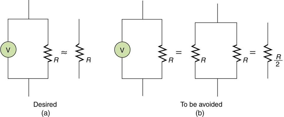
Part a shows a desired case in which the resistance of a voltmeter connected in parallel with a load resistor is essentially equivalent to the resistance of the load resistor along as long as the voltmeter’s resistance is much greater than that of the load resistor. Part b shows the case when the voltmeter’s resistance is approximately the same as that of the load resistor. This case should be avoided because the effective resistance is half that of the load resistor.
Figure 21.31 — 21.4 DC Voltmeters and Ammeters

Figure 21.31 (a) A voltmeter having a resistance much larger than the device ( R Voltmeter >> R R Voltmeter >> R ) with which it is in parallel produces a parallel resistance essentially the same as the device and does not appreciably affect the circuit being measured. (b) Here the voltmeter has the same resistance as the device ( R Voltmeter ≅ R R Voltmeter ≅ R ), so that the parallel resistance is half of what it is when the voltmeter is not connected. This is an example of a significant alteration of the circuit and is to be avoided.

Paul Peter Urone and Roger Hinrichs, College Physics 2E, OpenStax. · CC BY-NC-SA 4.0 · Original image ↗ · Access for free ↗
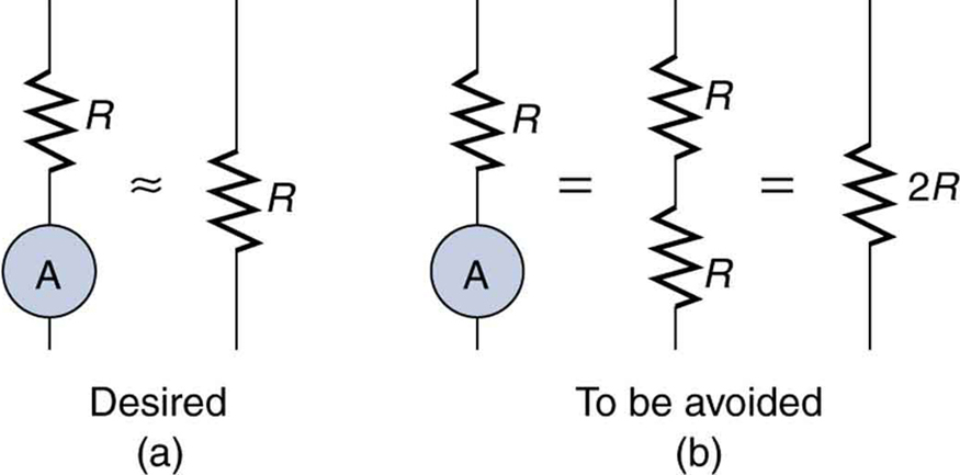
The figure shows two cases in which an ammeter is connected in series with a load resistor. Part a shows the desired case in which the resistance of the ammeter is much smaller than that of the load, and the total resistance is about the same as the load resistance. Part b shows the case to be avoided in which the ammeter has a resistance about the same as the load, and the total resistance is twice that of the load resistance.
Figure 21.32 — 21.4 DC Voltmeters and Ammeters

Figure 21.32 (a) An ammeter normally has such a small resistance that the total series resistance in the branch being measured is not appreciably increased. The circuit is essentially unaltered compared with when the ammeter is absent. (b) Here the ammeter’s resistance is the same as that of the branch, so that the total resistance is doubled and the current is half what it is without the ammeter. This significant alteration of the circuit is to be avoided.

Paul Peter Urone and Roger Hinrichs, College Physics 2E, OpenStax. · CC BY-NC-SA 4.0 · Original image ↗ · Access for free ↗

Source: 21.4 DC Voltmeters and Ammeters
120 terms, alphabetically ordered

Acid · ·

In the Brønsted–Lowry model, a substance that can donate a . Acidic have a higher activity than water.

Read explanation · OpenStax ↗
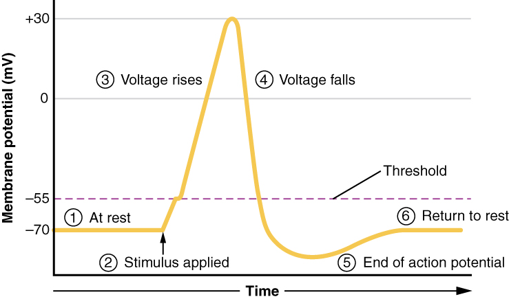
action potential

A regenerative -voltage change produced by voltage-dependent -channel activity.

Read explanation · OpenStax ↗
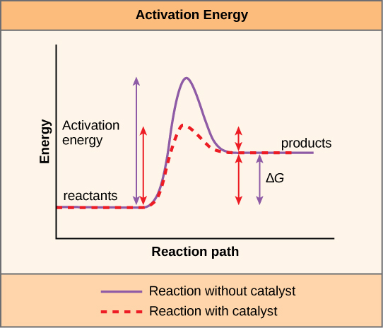
Activation energy ·

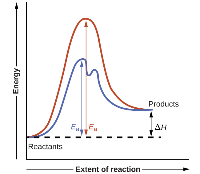
The energy barrier that must overcome to reach a and undergo .

Read explanation · OpenStax ↗
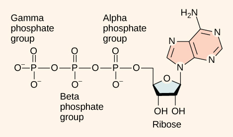
Adenosine triphosphate

An energy-carrying ; its powers many cellular processes, including cycles.

Read explanation · OpenStax ↗
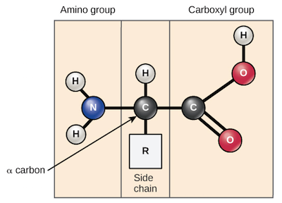
Alpha carbon · ·

The central carbon next to the carboxyl carbon. In a standard it binds an , hydrogen, and .

Read explanation · OpenStax ↗
Amide · · ·

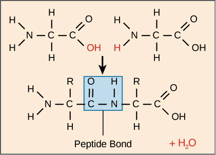
A group containing a carbon bonded to nitrogen. are amide linkages.

Read explanation · OpenStax ↗
Amino acid

A building block containing amino and and a characteristic .

Read explanation · OpenStax ↗
Amino acid residue · ·

The part of an incorporated into a chain. Residue can also describe another building block within a larger .

Read explanation · OpenStax ↗
Amino group · · ·

A nitrogen-containing . A free ’s amino group is typically (NH₃⁺) near physiological ; ’s ring nitrogen is an exception to this formula.

Read explanation · OpenStax ↗
ammeter

Current-measuring instrument placed in series with low internal .

Read explanation · OpenStax ↗
Amphipathic

Having both a region and a region, as in a or .

Read explanation · OpenStax ↗
Anion ·

An with a negative net .

Read explanation · OpenStax ↗
Aqueous solution ·

A in which water is the .

Read explanation · OpenStax ↗
Archaea ·

A of distinct from , with characteristic chemistry and -expression machinery.

Read explanation · OpenStax ↗
Atom

The smallest unit of an element that retains its chemical identity; it has a surrounded by .

Read explanation · OpenStax ↗
Bacteria ·

A of single-celled . Bacterial cells lack a -bound and are distinct from .

Read explanation · OpenStax ↗
Biomolecule

A made by or involved in living systems, including , , , and .

Read explanation · OpenStax ↗
Blotting ·

Transfer of separated or to a so a specific target can be detected.

Read explanation · Thermo Fisher ↗
Brønsted–Lowry base · · · · · · · · · · ·

In the Brønsted–Lowry model, a substance that can accept a . Basic solutions have lower activity than water.

Read explanation · OpenStax ↗
Carbohydrate

A class of including sugars and their , used for energy storage, structure, and recognition.

Read explanation · OpenStax ↗
Carbonyl group · ·

A carbon double-bonded to oxygen, C=O; present in and many other .

Read explanation · OpenStax ↗
Carboxyl group · ·

An , COOH. In free it is usually to COO⁻ near physiological .

Read explanation · OpenStax ↗
Catalyst · ·

A substance that speeds a by providing a pathway with lower and is regenerated rather than consumed overall.

Read explanation · OpenStax ↗
Cation ·

An with a positive net .

Read explanation · OpenStax ↗
Chemical compound ·

A substance containing of two or more different chemically combined in a definite composition.

Read explanation · OpenStax ↗
Chemical element

A substance defined by having the same number of , such as carbon or oxygen.

Read explanation · OpenStax ↗
Chemical reaction ·

A process that rearranges and chemical bonds, converting into .

Read explanation · OpenStax ↗
Chromatographic peak · ·

A rise and fall in detector signal as one or more components pass through the detector; a peak does not guarantee a single pure .

Read explanation · Agilent ↗
Chromatography

Separation of mixture components by their different interactions with a and a moving .

Read explanation · Waters ↗
Chromosome ·

An organized with associated that carries . A replicated chromosome has two .

Read explanation · OpenStax ↗
Codon

A sequence of three that specifies an or a stop signal.

Read explanation · OpenStax ↗
Concentration

The amount of a substance in a specified volume or mass of mixture.

Read explanation · OpenStax ↗
conduction

Thermal energy transfer through microscopic interactions without bulk matter flow.

Read explanation · OpenStax ↗
conductor

Material with that can move readily through it.

Read explanation · OpenStax ↗
Covalent bond · ·

A bond in which share pairs. and are covalent.

Read explanation · OpenStax ↗
Cysteine ·

An with a . Two cysteines can form a .

Read explanation · OpenStax ↗
Deoxyribonucleic acid

The that stores genetic information used to specify and sequences.

Read explanation · OpenStax ↗
Deprotonation

Removal of a from a or group; this changes its by minus one.

Read explanation · OpenStax ↗
Detergent

An substance that can associate with both water and material; detergents can disrupt or interactions.

Read explanation · Thermo Fisher ↗
Disulfide bond · · ·

A covalent sulfur–sulfur bond formed by of two , which can stabilize structure.

Read explanation · NCBI Bookshelf ↗
DNA replication

Copying so genetic information can be passed to daughter cells. Each guides a complementary new strand.

Read explanation · OpenStax ↗
Electric charge · · ·

An electrical property that can be positive or negative. Opposite charges attract and like charges repel; net charge is the sum of all charges on a particle.

Read explanation · OpenStax ↗
electric current

Rate of flow through a cross section, measured in amperes.

Read explanation · OpenStax ↗
electrical resistance ·

Voltage across a component divided by current through it under specified conditions.

Read explanation · OpenStax ↗
electromotive force

Energy supplied per unit by an electrical source.

Read explanation · OpenStax ↗
Electron

A negatively subatomic particle. Electron sharing and transfer determine much of chemical bonding.

Read explanation · OpenStax ↗
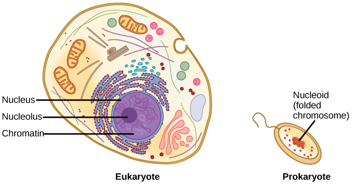
Eukaryote ·

An organism whose cells have a -enclosed ; animals, plants, fungi, and protists are eukaryotes.

Read explanation · OpenStax ↗
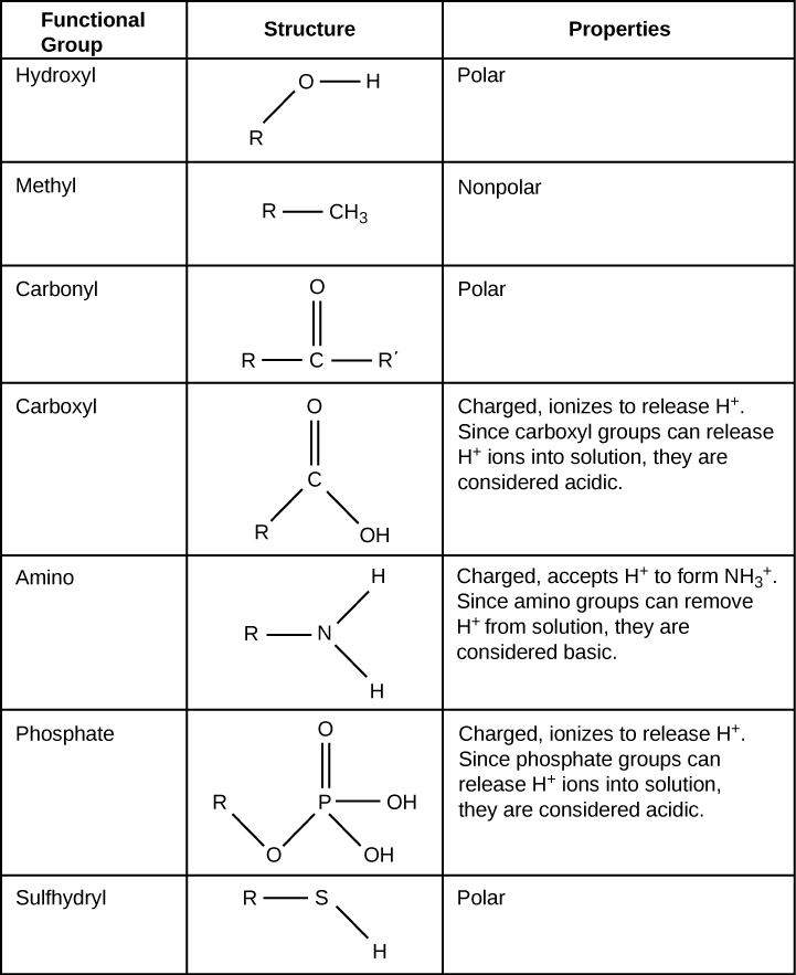
Functional group

A group of whose chemical behavior gives a characteristic and properties.

Read explanation · OpenStax ↗
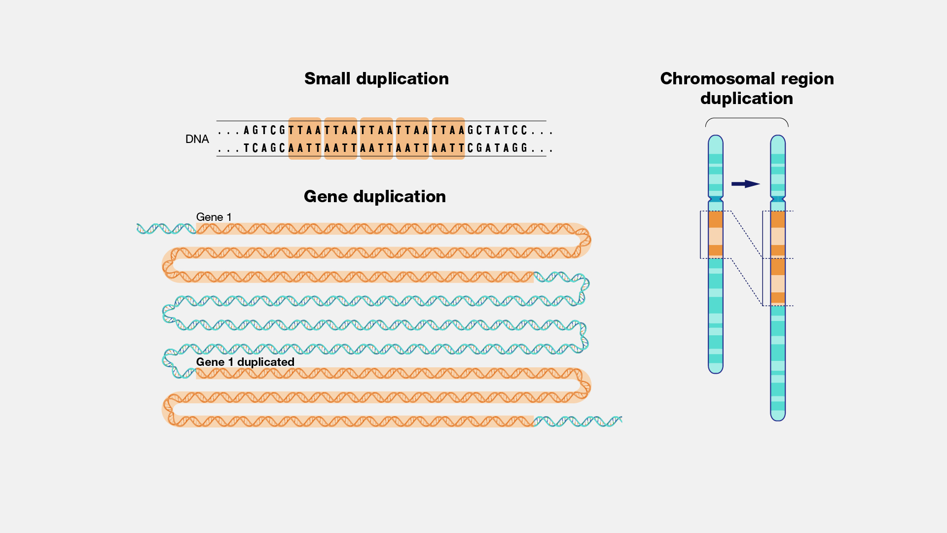
Gene

A sequence that contributes to a functional or , together with the information needed to express it.

Read explanation · OpenStax ↗
Gene expression

Production of a functional from a , including and, for -coding , .

Read explanation · NCBI Bookshelf ↗
Hydrogen ion · ·

A positively hydrogen species. H⁺ denotes a , which is hydrated in water; its activity determines .

Read explanation · OpenStax ↗
Hydrolysis

Breaking a chemical bond by adding water. hydrolysis separates .

Read explanation · OpenStax ↗
Hydrophilic

Interacting favorably with water, typically because a group is or .

Read explanation · OpenStax ↗
Hydrophobic

Interacting poorly with water. often gather in a ’s interior.

Read explanation · OpenStax ↗
Hydroxide ion ·

The negatively OH⁻. Basic contain a higher hydroxide ion activity than water at the same temperature.

Read explanation · OpenStax ↗
infrared spectroscopy ·

Method probing vibrational transitions through absorption of infrared light.

Read explanation · OpenStax ↗
Ion · ·

An or with a net because its numbers of and do not balance.

Read explanation · OpenStax ↗
Kirchhoff’s laws

conservation at circuit junctions and energy conservation around closed loops.

Read explanation · OpenStax ↗
linkage

A tendency of nearby on the same to be inherited together.

Read explanation · OpenStax ↗
Lipid

A broad class of largely or , including fats, , and steroids.

Read explanation · OpenStax ↗
locus

The specific position of a or other feature.

Read explanation · OpenStax ↗
Logarithm · · ·

The exponent needed to obtain a number from a chosen fixed number. For decimal logarithms, log₁₀(100) = 2 because 10² = 100; uses the negative decimal logarithm of activity.

Read explanation · OpenStax ↗
magnetic field

field that exerts forces on moving and magnetic moments.

Read explanation · OpenStax ↗
mechanical power

Rate of energy transfer, measured in watts.

Read explanation · OpenStax ↗
mechanical work

Energy transferred by a force acting through ; the force component parallel to motion contributes.

Read explanation · OpenStax ↗
Membrane · · · ·

A thin boundary or sheet. Cell membranes are bilayers containing ; membranes are synthetic supports that hold or for detection.

Read explanation · OpenStax ↗
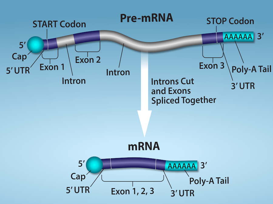
Messenger RNA ·

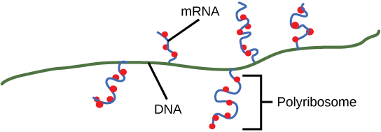
An that carries coding information used by to synthesize a .

Read explanation · OpenStax ↗
Mobile phase

The moving fluid that carries a sample through a system.

Read explanation · Waters ↗
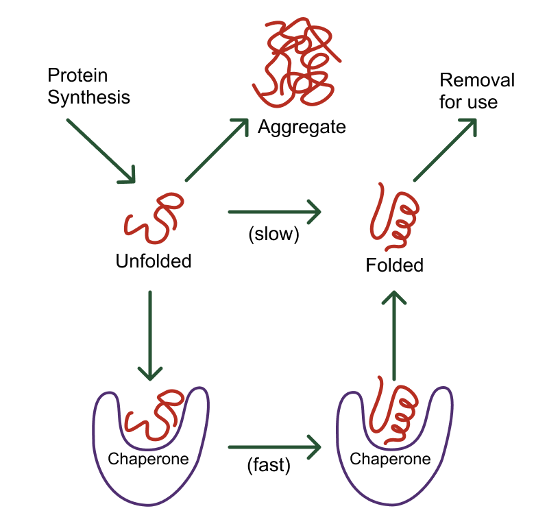
Molecular chaperone · ·

A that assists other in folding or prevents , without specifying their sequence.

Read explanation · NCBI Bookshelf ↗
Molecule

Two or more joined by . A molecule may be electrically or carry a .

Read explanation · OpenStax ↗
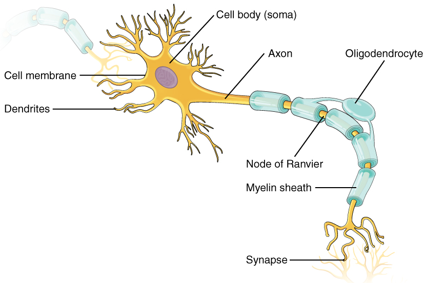
Myelin

A -rich insulating sheath around many nerve axons that supports efficient signal .

Read explanation · NHGRI / NIH ↗
neuron

An electrically excitable cell specialized for receiving and transmitting information.

Read explanation · OpenStax ↗
Neutral

Having no net . For a , neutral instead means equal and activities; its is about 7 at 25 °C.

Read explanation · OpenStax ↗
Nitrogenous base · · ·

A nitrogen-containing ring component of ; its pairing interactions help specify sequences.

Read explanation · OpenStax ↗
Nonpolar ·

Lacking a substantial separation of . Nonpolar groups generally interact poorly with water.

Read explanation · OpenStax ↗
Nucleic acid

A of , such as or , used in information storage, expression, and other cellular functions.

Read explanation · OpenStax ↗
Nucleotide

A joined to a sugar and one or more .

Read explanation · OpenStax ↗
Nucleus ·

A -enclosed compartment containing most of a cell’s .

Read explanation · OpenStax ↗
Ohm’s law

Relationship V = for an ohmic at fixed conditions.

Read explanation · OpenStax ↗
Oxidation ·

Loss of or an increase in oxidation state. Oxidizing two can form a .

Read explanation · OpenStax ↗
Peptide

A chain of joined by ; the term commonly describes chains shorter than a typical .

Read explanation · OpenStax ↗
Peptide bond ·

A covalent between the carboxyl carbon of one and the amino nitrogen of the next.

Read explanation · OpenStax ↗
pH

A measure of , defined as the negative of activity. Lower pH means greater ; pH influences .

Read explanation · OpenStax ↗
Phosphate group ·

A phosphorus-containing group bonded to oxygens; phosphate groups occur in , , and modified .

Read explanation · OpenStax ↗
Phospholipid

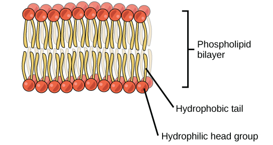
An with a -containing region and tails; a major component of cellular .

Read explanation · OpenStax ↗
physical displacement ·

Signed or difference between final and initial position.

Read explanation · OpenStax ↗
Polar

Having an uneven distribution of . Polar groups often interact favorably with water.

Read explanation · OpenStax ↗
Polymer

A large made from many linked molecular building blocks.

Read explanation · OpenStax ↗
Polypeptide

A chain of connected by . A functional can contain one or several such chains.

Read explanation · OpenStax ↗
Prokaryote ·

An organism whose cells lack a -bound ; and are prokaryotes.

Read explanation · OpenStax ↗
Proline ·

An whose loops back to the nitrogen, restricting rotation and often creating bends.

Read explanation · OpenStax ↗
Protein

One or more folded chains that perform biological roles such as , transport, signaling, or structural support.

Read explanation · OpenStax ↗
Protein aggregation · ·

Association of into larger clusters, often when exposed surfaces of unfolded stick together.

Read explanation · NCBI Bookshelf ↗
Protein backbone ·

The repeating nitrogen–alpha-carbon– chain of a , excluding its variable .

Read explanation · OpenStax ↗
Protein domain · ·

A region of a that forms a recognizable structural or functional unit.

Read explanation · OpenStax ↗
Proton

A positively subatomic particle. In – chemistry, donating a proton means transferring a .

Read explanation · OpenStax ↗
Protonation

Addition of a to an , , or ; this changes its by plus one.

Read explanation · OpenStax ↗
R group · ·

The variable side chain attached to an ’s . It determines identity, , , and chemical behavior.

Read explanation · OpenStax ↗
Reactant

A starting substance transformed during a .

Read explanation · OpenStax ↗
Reaction intermediate · ·

A species formed in one step and consumed in another. It occupies a local energy minimum between .

Read explanation · OpenStax ↗
Reaction product ·

A substance formed by a .

Read explanation · OpenStax ↗
reaction quotient

-to- activity ratio with stoichiometric exponents at the current composition.

Read explanation · OpenStax ↗
resistivity

Material property relating to length and cross-sectional area.

Read explanation · OpenStax ↗
Rho factor · · ·

A -dependent factor that acts on to help terminate .

Read explanation · OpenStax ↗
Ribonucleic acid ·

A with roles in , regulation, and ; carries -coding information.

Read explanation · OpenStax ↗
Ribosome ·

A complex of and that translates into a .

Read explanation · OpenStax ↗
Sister chromatid

One of the two copies of a produced by . An intact sister chromatid can supply a template for accurate repair.

Read explanation · Biology LibreTexts / Oregon State University ↗
Solubility ·

The amount of a substance that can dissolve in a under specified conditions. Soluble means able to dissolve; insoluble means only very slightly soluble in that .

Read explanation · OpenStax ↗
Solute

A dissolved component of a .

Read explanation · OpenStax ↗
Solution

A homogeneous mixture in which are dissolved in a .

Read explanation · OpenStax ↗
Solvent

The component of a that dissolves other substances, usually the component present in the greatest amount.

Read explanation · OpenStax ↗
spatial vector ·

Quantity with both magnitude and direction, combined by adding components.

Read explanation · OpenStax ↗
Stationary phase

The material that remains fixed in a system.

Read explanation · Waters ↗
Template strand · · ·

A preexisting strand whose sequence guides complementary nucleic- synthesis.

Read explanation · OpenStax ↗
Thiol group · · · ·

A sulfur bonded to hydrogen, –SH. thiols can form through .

Read explanation · OpenStax ↗
Transcription

Synthesis of using a template.

Read explanation · OpenStax ↗
Transition state

A fleeting, high-energy arrangement at a barrier. It is an energy maximum along the path, rather than a stable .

Read explanation · OpenStax ↗
Translation ·

Synthesis of a on a using the sequence of in .

Read explanation · OpenStax ↗
velocity

Rate of change of position, including direction.

Read explanation · OpenStax ↗
voltmeter

Potential-difference instrument placed in parallel with high internal .

Read explanation · OpenStax ↗

College Physics 2E 20 — Section Summary

OpenStax · College Physics 2E 20 — Section Summary ↗
Instructional page including learning objectives, examples, figures, source tables and questions. Site navigation and embedded media players are omitted; source media links remain available.

20.1 Current

  • I is the rate at which flows, given by
    I=ΔQΔt ,
    where ΔQ is the amount of passing through an area in time Δt.
  • The direction of conventional current is taken as the direction in which positive moves.
  • The SI unit for current is the ampere (A), where 1 A = 1 C/s.
  • Current is the flow of free , such as and .
  • Drift vd is the average speed at which these move.
  • Current I is proportional to drift vd, as expressed in the relationship I=nqAvd. Here, I is the current through a wire of cross-sectional area A. The wire’s material has a free- density n, and each has and a drift vd.
  • Electrical signals travel at speeds about 1012 times greater than the drift of free .

20.2 Ohm’s Law: Resistance and Simple Circuits

  • A simple circuit is one in which there is a single voltage source and a single .
  • One statement of gives the relationship between current I , voltage V , and R in a simple circuit to be I=VR.
  • has units of ohms ( Ω ), related to volts and amperes by 1 Ω= 1 V/A.
  • There is a voltage or drop across a resistor, caused by the current flowing through it, given by V=IR.

20.3 Resistance and Resistivity

  • The R of a cylinder of length L and cross-sectional area A is R=ρLA, where is the of the material.
  • Values of in Table 20.1 show that materials fall into three groups—conductors, semiconductors, and insulators.
  • Temperature affects ; for relatively small temperature changes ΔT, is ρ=ρ0(1 +αΔT), where ρ0 is the original and α is the temperature coefficient of .
  • Table 20.2 gives values for α, the temperature coefficient of .
  • The R of an object also varies with temperature: R=R0(1 +αΔT), where R0 is the original , and R is the after the temperature change.

20.4 Electric Power and Energy

  • Electric P is the rate (in watts) that energy is supplied by a source or dissipated by a device.
  • Three expressions for electrical are
    P=IV,
    P=V2R,

    and

    P=I2R.
  • The energy used by a device with a P over a time t is E=Pt.

20.5 Alternating Current versus Direct Current

  • Direct current (DC) is the flow of in only one direction. It refers to systems where the source voltage is constant.
  • The voltage source of an alternating current (AC) system puts out V=V0sin 2πft, where V is the voltage at time t, V0 is the voltage, and f is the frequency in hertz.
  • In a simple circuit, I=V/R and AC current is I=I0sin 2πft, where I is the current at time t, and I0=V0/R is the current.
  • The average AC is Pave=12I0V0.
  • Average (rms) current Irms and average (rms) voltage Vrms are Irms=I02 and Vrms=V02, where rms stands for root mean square.
  • Thus, Pave=IrmsVrms.
  • for AC is Irms=VrmsR.
  • Expressions for the average of an AC circuit are Pave= Irms Vrms, Pave = Vrms2R, and Pave= Irms2R, analogous to the expressions for DC circuits.

20.6 Electric Hazards and the Human Body

  • The two types of electric hazards are thermal (excessive ) and shock (current through a person).
  • Shock severity is determined by current, path, duration, and AC frequency.
  • Table 20.3 lists shock hazards as a function of current.
  • Figure 20.22 graphs the threshold current for two hazards as a function of frequency.

20.7 Nerve Conduction–Electrocardiograms

  • Electric potentials in and other cells are created by ionic differences across semipermeable .
  • Stimuli change the permeability and create that propagate along .
  • sheaths speed this process and reduce the needed energy input.
  • This process in the heart can be measured with an electrocardiogram (ECG).

21.4 DC Voltmeters and Ammeters
OpenStax · 21.4 DC Voltmeters and Ammeters ↗
Instructional page including learning objectives, examples, figures, source tables and questions. Site navigation and embedded media players are omitted; source media links remain available.

Learning Objectives

By the end of this section, you will be able to:

  • Explain why a must be connected in parallel with the circuit.
  • Draw a diagram showing an correctly connected in a circuit.
  • Describe how a galvanometer can be used as either a or an .
  • Find the that must be placed in series with a galvanometer to allow it to be used as a with a given reading.
  • Explain why measuring the voltage or current in a circuit can never be exact.

Voltmeters measure voltage, whereas ammeters measure current. Some of the meters in automobile dashboards, digital cameras, cell phones, and tuner-amplifiers are voltmeters or ammeters. (See Figure 21.26.) The internal construction of the simplest of these meters and how they are connected to the system they monitor give further insight into applications of series and parallel connections.

This photograph shows the instruments on a gray Volkswagen Vento dashboard, including the speedometer, odometer, and fuel and temperature gauges, showing some readings.
Figure 21.26 — 21.4 DC Voltmeters and Ammeters
Figure 21.26 The fuel and temperature gauges (far right and far left, respectively) in this 1996 Volkswagen are voltmeters that register the voltage output of “sender” units, which are hopefully proportional to the amount of gasoline in the tank and the engine temperature. (credit: Christian Giersing)

Paul Peter Urone and Roger Hinrichs, College Physics 2E, OpenStax. (credit: Christian Giersing) · CC BY-NC-SA 4.0 · Original image ↗ · Access for free ↗

Voltmeters are connected in parallel with whatever device’s voltage is to be measured. A parallel connection is used because objects in parallel experience the same potential difference. (See Figure 21.27, where the is represented by the symbol V.)

Ammeters are connected in series with whatever device’s current is to be measured. A series connection is used because objects in series have the same current passing through them. (See Figure 21.28, where the is represented by the symbol A.)

Part a shows a schematic drawing of a circuit with a voltage source and its internal resistance, in series with two load resistors R sub one and R sub two having two probes of a voltmeter connected in parallel with each component. There is another resistor in series to close the circuit. Part b shows a photograph of a black voltmeter connected to two inputs on an electrical device, with a digital readout of the voltage across the source as an L E D display.
Figure 21.27 — 21.4 DC Voltmeters and Ammeters
Figure 21.27 (a) To measure potential differences in this series circuit, the voltmeter (V) is placed in parallel with the voltage source or either of the resistors. Note that terminal voltage is measured between points a and b. It is not possible to connect the voltmeter directly across the emf without including its internal resistance, r r . (b) A digital voltmeter in use. (credit: Messtechniker, Wikimedia Commons)

Paul Peter Urone and Roger Hinrichs, College Physics 2E, OpenStax. (credit: Messtechniker, Wikimedia Commons) · CC BY-NC-SA 4.0 · Original image ↗ · Access for free ↗
The diagram of an electric circuit shows a voltage source of e m f script E and internal resistance r and two resistive loads R sub one and R sub two. All are connected in series with an ammeter A.
Figure 21.28 — 21.4 DC Voltmeters and Ammeters

Figure 21.28 An ammeter (A) is placed in series to measure current. All of the current in this circuit flows through the meter. The ammeter would have the same reading if located between points d and e or between points f and a as it does in the position shown. (Note that the script capital E stands for emf, and r r stands for the internal resistance of the source of potential difference.)

Paul Peter Urone and Roger Hinrichs, College Physics 2E, OpenStax. · CC BY-NC-SA 4.0 · Original image ↗ · Access for free ↗

Analog Meters: Galvanometers

Analog meters have a needle that swivels to point at numbers on a scale, as opposed to digital meters, which have numerical readouts similar to a hand-held calculator. The heart of most analog meters is a device called a galvanometer, denoted by G. Current flow through a galvanometer, IG, produces a proportional needle deflection. (This deflection is due to the force of a upon a current-carrying wire.)

The two crucial characteristics of a given galvanometer are its and current sensitivity. Current sensitivity is the current that gives a full-scale deflection of the galvanometer’s needle, the maximum current that the instrument can measure. For example, a galvanometer with a current sensitivity of 50 μA has a maximum deflection of its needle when 50 μA flows through it, reads half-scale when 25 μA flows through it, and so on.

If such a galvanometer has a 25-Ω , then a voltage of only V=IR=50 μA25 Ω=1.25 mV produces a full-scale reading. By connecting resistors to this galvanometer in different ways, you can use it as either a or that can measure a broad range of voltages or currents.

Galvanometer as

Figure 21.29 shows how a galvanometer can be used as a by connecting it in series with a large , R. The value of the R is determined by the maximum voltage to be measured. Suppose you want 10 V to produce a full-scale deflection of a containing a 25-Ω galvanometer with a 50-μA sensitivity. Then 10 V applied to the meter must produce a current of 50 μA. The total must be

Rtot=R+r=VI=10 V50 μA=200 kΩ, or
21.68
R=Rtot−r=200 kΩ−25Ω≈200 kΩ.
21.69

(R is so large that the galvanometer , r, is nearly negligible.) Note that 5 V applied to this produces a half-scale deflection by producing a 25-μA current through the meter, and so the ’s reading is proportional to voltage as desired.

This would not be useful for voltages less than about half a volt, because the meter deflection would be small and difficult to read accurately. For other voltage ranges, other are placed in series with the galvanometer. Many meters have a choice of scales. That choice involves switching an appropriate into series with the galvanometer.

The drawing shows a voltmeter, which is a circuit with a large resistance in series with a galvanometer, along with its internal resistance.
Figure 21.29 — 21.4 DC Voltmeters and Ammeters
Figure 21.29 A large resistance R R placed in series with a galvanometer G produces a voltmeter, the full-scale deflection of which depends on the choice of R R . The larger the voltage to be measured, the larger R R must be. (Note that r r represents the internal resistance of the galvanometer.)

Paul Peter Urone and Roger Hinrichs, College Physics 2E, OpenStax. · CC BY-NC-SA 4.0 · Original image ↗ · Access for free ↗

Galvanometer as

The same galvanometer can also be made into an by placing it in parallel with a small R, often called the shunt , as shown in Figure 21.30. Since the shunt is small, most of the current passes through it, allowing an to measure currents much greater than those producing a full-scale deflection of the galvanometer.

Suppose, for example, an is needed that gives a full-scale deflection for 1.0 A, and contains the same 25-Ω galvanometer with its 50-μA sensitivity. Since R and r are in parallel, the voltage across them is the same.

These drops are IR=IGr so that IR=IGI=Rr. Solving for R, and noting that IG is 50 μA and I is 0.999950 A, we have

R=rIGI=(25Ω)50 μA0.999950 A=1.25×10⁻³Ω.
21.70
A resistance R is placed in parallel with a galvanometer G having an internal resistance r to produce an ammeter.
Figure 21.30 — 21.4 DC Voltmeters and Ammeters
Figure 21.30 A small shunt resistance R R placed in parallel with a galvanometer G produces an ammeter, the full-scale deflection of which depends on the choice of R R . The larger the current to be measured, the smaller R R must be. Most of the current ( I I ) flowing through the meter is shunted through R R to protect the galvanometer. (Note that r r represents the internal resistance of the galvanometer.) Ammeters may also have multiple scales for greater flexibility in application. The various scales are achieved by switching various shunt resistances in parallel with the galvanometer—the greater the maximum current to be measured, the smaller the shunt resistance must be.

Paul Peter Urone and Roger Hinrichs, College Physics 2E, OpenStax. · CC BY-NC-SA 4.0 · Original image ↗ · Access for free ↗

Taking Measurements Alters the Circuit

When you use a or , you are connecting another resistor to an existing circuit and, thus, altering the circuit. Ideally, voltmeters and ammeters do not appreciably affect the circuit, but it is instructive to examine the circumstances under which they do or do not interfere.

First, consider the , which is always placed in parallel with the device being measured. Very little current flows through the if its is a few orders of magnitude greater than the device, and so the circuit is not appreciably affected. (See Figure 21.31(a).) (A large in parallel with a small one has a combined essentially equal to the small one.) If, however, the ’s is comparable to that of the device being measured, then the two in parallel have a smaller , appreciably affecting the circuit. (See Figure 21.31(b).) The voltage across the device is not the same as when the is out of the circuit.

Part a shows a desired case in which the resistance of a voltmeter connected in parallel with a load resistor is essentially equivalent to the resistance of the load resistor along as long as the voltmeter’s resistance is much greater than that of the load resistor. Part b shows the case when the voltmeter’s resistance is approximately the same as that of the load resistor. This case should be avoided because the effective resistance is half that of the load resistor.
Figure 21.31 — 21.4 DC Voltmeters and Ammeters
Figure 21.31 (a) A voltmeter having a resistance much larger than the device ( R Voltmeter >> R R Voltmeter >> R ) with which it is in parallel produces a parallel resistance essentially the same as the device and does not appreciably affect the circuit being measured. (b) Here the voltmeter has the same resistance as the device ( R Voltmeter ≅ R R Voltmeter ≅ R ), so that the parallel resistance is half of what it is when the voltmeter is not connected. This is an example of a significant alteration of the circuit and is to be avoided.

Paul Peter Urone and Roger Hinrichs, College Physics 2E, OpenStax. · CC BY-NC-SA 4.0 · Original image ↗ · Access for free ↗

An is placed in series in the branch of the circuit being measured, so that its adds to that branch. Normally, the ’s is very small compared with the of the devices in the circuit, and so the extra is negligible. (See Figure 21.32(a).) However, if very small load are involved, or if the is not as low in as it should be, then the total series is significantly greater, and the current in the branch being measured is reduced. (See Figure 21.32(b).)

A practical problem can occur if the is connected incorrectly. If it was put in parallel with the resistor to measure the current in it, you could possibly damage the meter; the low of the would allow most of the current in the circuit to go through the galvanometer, and this current would be larger since the effective is smaller.

The figure shows two cases in which an ammeter is connected in series with a load resistor. Part a shows the desired case in which the resistance of the ammeter is much smaller than that of the load, and the total resistance is about the same as the load resistance. Part b shows the case to be avoided in which the ammeter has a resistance about the same as the load, and the total resistance is twice that of the load resistance.
Figure 21.32 — 21.4 DC Voltmeters and Ammeters
Figure 21.32 (a) An ammeter normally has such a small resistance that the total series resistance in the branch being measured is not appreciably increased. The circuit is essentially unaltered compared with when the ammeter is absent. (b) Here the ammeter’s resistance is the same as that of the branch, so that the total resistance is doubled and the current is half what it is without the ammeter. This significant alteration of the circuit is to be avoided.

Paul Peter Urone and Roger Hinrichs, College Physics 2E, OpenStax. · CC BY-NC-SA 4.0 · Original image ↗ · Access for free ↗

One to the problem of voltmeters and ammeters interfering with the circuits being measured is to use galvanometers with greater sensitivity. This allows construction of voltmeters with greater and ammeters with smaller than when less sensitive galvanometers are used.

There are practical limits to galvanometer sensitivity, but it is possible to get analog meters that make measurements accurate to a few percent. Note that the inaccuracy comes from altering the circuit, not from a fault in the meter.
Connections: Limits to Knowledge

Making a measurement alters the system being measured in a manner that produces uncertainty in the measurement. For macroscopic systems, such as the circuits discussed in this module, the alteration can usually be made negligibly small, but it cannot be eliminated entirely. For submicroscopic systems, such as , , and smaller particles, measurement alters the system in a manner that cannot be made arbitrarily small. This actually limits knowledge of the system—even limiting what nature can know about itself. We shall see profound implications of this when the Heisenberg uncertainty principle is discussed in the modules on quantum mechanics.

There is another measurement technique based on drawing no current at all and, hence, not altering the circuit at all. These are called null measurements and are the topic of Null Measurements. Digital meters that employ solid-state electronics and null measurements can attain accuracies of one part in 106.

Check Your Understanding

Digital meters are able to detect smaller currents than analog meters employing galvanometers. How does this explain their ability to measure voltage and current more accurately than analog meters?

Since digital meters require less current than analog meters, they alter the circuit less than analog meters. Their as a can be far greater than an analog meter, and their as an can be far less than an analog meter. Consult Figure 21.27 and Figure 21.28 and their discussion in the text.

PhET Explorations

Circuit Construction Kit (DC Only), Virtual Lab

Construct the circuit shown and use the simulation’s and to measure the current in the circuit and the voltage across each component.